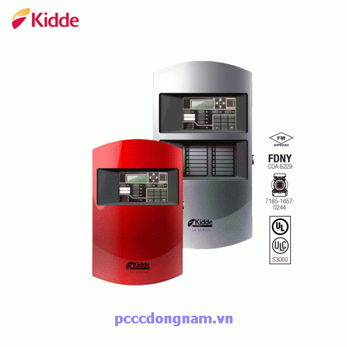
Intelligent Fire Alarm Systems VS1
Kidde brand intelligent life safety systems offer the power of highend intelligent processing in configurations that deliver uncomplicated solutions for small to mid-sized applications. With intelligent detection, electronic addressing, automatic device mapping, optional Ethernet
® connectivity, and a full line of easily-configured option cards and modules, these flexible systems offer versatility that benefits building owners and contractors alike
The VS1 provides one Class A or Class B intelligent device loop that supports up to 64 device addresses, and two Class B Notification Appliance Circuits (NACs). Optional Class A device wiring is available with the use of a module
Features
• Auto-programming speeds installation time
• Supports V-Series intelligent modules and detectors
• Form C contacts for alarm and trouble, Form A for supervisory
• Electronic addressing with automatic device mapping
• Optional Ethernet port for diagnostics, programming and a variety of system reports
• Two programmable switches with LEDs and custom labeling
• Supports Genesis horn silence over two wires, and UL 1971-compliant strobe synchronization
• Supports GSA-REL releasing module for fire suppression
• Class B or Class A wiring
• Ground fault detection by module
• Supports up to eight serial annunciators, (LCD, LED-only, and graphic interface)
• Can use existing wiring for most retrofit applications
• Upload/download remotely or locally
• Two-level maintenance alert reporting
• Pre-alarm and alarm verification by point
• Adjustable detector sensitivity
• 4 x 20 character backlit LCD display
• Optional earthquake hardening: seismic Importance Factor 1.5
• Standalone operation
• Transmission test frequency by hour
• Alarm ON command manually activates alarm condition
Dimensions
.png)
System Layout
.png)
Each VS1 panel ships with one device loop controller that supports 64 devices of any type. This panel’s device capacity cannot be expanded.
Panel Layout
.png)
1 Transformer
2 Main AC wiring block & fuse holder
3 RS-232 card connector (J3)
4 Dialer card connection (J8)
5 Ethernet card connector (J1)
6 Main circuit board
7 Panel backbox enclosure
8 Operator interface
9 SLC card connector (J7)
10 Class A card connector (J2)
11 Tie wrap mounts
12 LED expander connector (J6)
13 Standby batteries
Specifications
| Model | VS1 | VS4 |
| Device loops | 1 loop Class B or Class A (Styles 4, 6, 7) supporting up to 64 device addresses (any combination of detectors and modules) Maximum T-taps: 63 (each device can be on its own branch) | 1 loop, expandable to 4, Class A or B (Styles 4, 6, 7), each loop supporting up to 250 device addresses (125 detectors and 125 modules max.). Addresses 1 to 125 are for detectors and addresses 126 to 250 are for modules Maximum T-taps/loop: 124 |
| Notification appliance circuits |
2 Class B (Style Y), Class A (Style Z) optional 3.75 A FWR total at 120/230 VAC 60 Hz 3.0 A FWR total at 230 VAC 50 Hz 2.5 A FWR each max. per circuit |
4 Class B (Style Y) or 2 Class A (Style Z) 6.0 A FWR total at 120/230 VAC 60 Hz 5.0 A FWR total at 230 VAC 50 Hz 2.5 A FWR each max. per circuit |
| Primary power |
120 VAC, 60 Hz, 1.3 A max. 230 VAC, 50-60 Hz, 0.62 A max. |
120 VAC, 60 Hz, 2.0 A max. 230 VAC, 50-60 Hz, 0.97 A max. |
| Base panel current standby | 155 mA | 172 mA |
| Base panel current alarm | 204 mA | 267 mA |
| Input zones | 16 max | 32 max. |
| Remote annunciator |
8 drops max., RS-485 Class B, Class A is optional Data line length: 4,000 ft. (1,219 m) |
8 drops max., RS-485 Class A or B Data line length: 4,000 ft. (1,219 m) |
| Operating voltage | 24 VDC pane | |
| Auxiliary power output circuit |
Aux power 1: 500 mA, 24 VDC Aux power 2: 500 mA, 24 VDC (1 A possible if you reduce total available NAC power by 500 mA) Output: 28.3 to 21.9 VDC, special application Note: For a list of compatible devices, see the VS1 and VS4 Series Compatibility List (P/N 3102354-EN) |
|
| Loop circuit |
Maximum loop resistance: 66 Ω Maximum loop capacitance: 0.5 µF Communication line voltage: Maximum 20.6 V peak-to-peak Operating current (fully loaded loop) Stand by: 55 mA/45 mA Alarm: 125 mA/115 mA (not including two-wire smoke modules) Circuit current: 0.5 A max. Style 4, 6, and 7 wiring Max. resistance between isolators: Limited only by overall wire run lengths 64 isolators maximum per loop (total both isolator bases and modules) |
|
| Batteries |
Type: Sealed lead acid Voltage: 24 VDC Charging current: 2.47 A max. Amp hour capacity: 26 Ah Standby operation: 24 hour or 60 hour Placement: Up to two 10 Ah batteries will fit in the VS1 control panel cabinet and two 18 Ah batteries will fit in the VS4 control panel cabinet. If larger batteries are required, use a battery cabinet. |
|
| SA-DACT dialer |
Phone line type: One or two loop-start lines on a public, switched network Phone line connector: RJ-31/38X (C31/38X) Communication formats: Contact ID (SIA DC-05) Operating current Standby/Alarm: 41 mA Max.: 100 mA FCC registration number: GESAL01BSADACT Industry Canada Registration number: 3944A-SADACT Ringer equivalence number: 0.1B |
|
| Ground fault impedance | 0 to 5 kΩ | |
| Alarm contact | Form C N.O. 24 VDC at 1 A (resistive load) | |
| Trouble contact | Form C 24 VDC at 1 A (resistive load) | |
| Supervisory contact | Form A N.O. 24 VDC at 1 A (resistive load) | |
| Environmenta | Temperature: 0 to 49°C (32 to 120°F) Relative humidity: 0 to 93% noncondensing | |
| Terminal rating | All terminals rated for 12 to 18 AWG (0.75 to 2.5 mm² | |
Ordering Information
VS1 Fire Alarm Systems
.png)
Option Cards
.png)
Accessories
.png)
Programming Tools
.png)




Have 0 comment, evaluate about Intelligent Fire Alarm Systems VS1
TVAdministratorsAdministrators