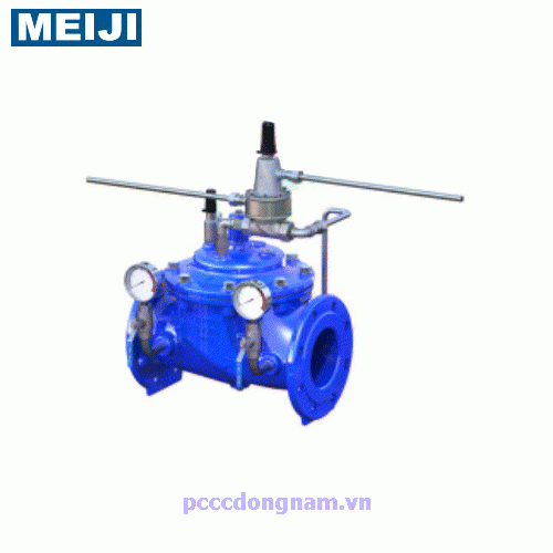
Meiji FIG 1005N Pressure Relief Valve
DIFFERENTIAL RELIEF PILOT CONTROL VALVE PN16/25 Hydraulic pressure relief valve structure: stainless steel pressure relief valve, safety valve suitable for all types of valves1. Main valve 2. Need valve 3. Differential relief control 4. Ball valve 5. Inlet pressure gauge 6. Outlet pressure gauge 7. Filter the letter Y
Numerical description
Type: Pressure control valve, - Construction: stainless steel - Size: DN 50 - 800 mm - Working pressure: 16/25 bar. - Test pressure : Shell: 24/37.5 bar - Working temperature: -10°C to 80°C - Meets BS EN 1074-5, ISO 5208, BS EN 12266.1, BS EN 558-1 standards.
- Flange connection to JIS 10/16K, BS4504 PN16/25, ANSI #150/300.
• The main valve will open against the system pressure differential whenever the pilot (adjustable) setting is exceeded. • Main valve must be hydraulically operated, single diaphragm actuated. Y-pattern valves will not be allowed. The valve shall contain a disc assembly and a diaphragm that forms a sealed cavity below the valve cover, separating the operating pressure the line pressure. The diaphragms are constructed of reinforced nylon (EPDM + nylon Fabric), and are not sealed directly to the valve seat and must be fully supported by the valve body and cover. Diaphragm construction will not be allowed and there will be no piston operating the main valve or any pilot controls.
• Main valve body and cover shall be ductile iron GGG 500-7 and all internal castings shall be Ductile Iron or (SUS 304) stainless. All ductile iron components, including body and housing, will be lined with an NSF 61 certified Epoxy coating applied by electrostatic fusion. All main valve regulating components (valve seat and disc guide) will be stainless steel. The valve body and cover must be machined with a 360 degree locating lip to ensure proper alignment.
• The disc unit and diaphragm must contain Buna-N rubber composite (EPDM + Nylon cloth) that is securely held on either side by the disc holder and disc guide. Membrane assembly using bolts or cap screws to hold the component will not be allowed.
• The contact part of the EPDM+ Fabric must be in contact with the valve seat and sealed. The disc and diaphragm assemblies must be guided by two separate bearings, one installed in the valve cover and the other concentrically located in the valve seat, to prevent deflection and to ensure positive disc contact. Central guide valve will not be allowed. All necessary repairs must be made the top of the valve while the body remains in alignment.
• Pilot control system for valve must have external Y filter, differential relief pilot and ball valve on all body connections. All pilot control systems will use stainless steel tubing and are suitable regardless of valve size.
Functions
• Throttle for key constant difference between two pressure points.
• Maintain a preset pressure difference between high and low pressure areas.
• Opens when differential pressure is increased.
• Closes when the differential pressure is reduced.
• Low pressure sense flow field is installed.
• Adjust the closing speed.
• The setpoint is adjustable.
• High pressure sense flow field is installed.



Have 0 comment, evaluate about Meiji FIG 1005N Pressure Relief Valve
TVAdministratorsAdministrators