Physical Data
.png)
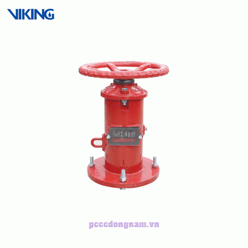
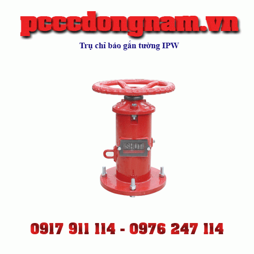
Specifications Horizontal Wall Post Indicator IPW
• Indicator of “Open” and “Shut” positions
• Used to operate post indicator valves
• 12” OD post flange for wall mounting
• Handwheel operation
• Internally and externally coated in red epoxy RAL3000
• 1m long stem bar is supplied
Materials List Horizontal Wall Post Indicator IPW
.png)
Installation Horizontal Wall Post Indicator IPW
NOTE: Ensure that the post indicator valve is in the fully open position before installing the Wall Post Indicator.
1.) Make the hole through the wall Make a clearance hole that is at least 120mm
- (4.7”) in diameter but not greater than 180mm
- (7.1”) in diameter through the mounting wall. The clearance hole must be on-center and concentric with the operating nut of the post indicator valve. NOTE: A DN100 / 4” (114.3mm Outside Diameter) length of pipe can be used to line the inside of the through hole. Pipe of this diameter will fit snugly a machined mating hole on the flange side the Body (1) of the Wall Post Indicator.
2. ) Drill the Mounting Holes Drill 4 equally spaced holes on a 267 mm (10.5”) bolt circle the mounting wall using a ¾” (19mm) drill bit. The bolt circle must be concentric and on center with the operating nut of the post indicator valve.
3. ) Mount the Wall Post Indicator Bolt the flange of the Body (1) of the Wall Post Indicator to the wall using 4 bolts (18 & 19).
4.) Remove the Cover With the Body (1) flange of the Wall Post Indicator securely bolted to the mounting wall, remove the Cover (5) by removing the two Bolts (4) and Nuts (3). Slide the Cover (5) off of the Wall Post Indicator Body (1).
5.) and measure the Stem Rod With the Cover (5) still separated the Body (1), slide the Stem (20), Cotter Pin (21) and Socket (22) assembly through the Wall Post Indicator Body (1) and through the wall such that the Socket(22) fully engages with the operating nut of the non-rising stem gate valve. With the Socket (22) fully engaged on the operating nut of the nonrising stem gate valve, put a mark on the Stem (20) that is between 32mm (1.25”) below the top surface of the Body (1) but not more than 50mm (2”) above the top surface of the Body (1).
6.) Cut the Stem Rod Cut the stem rod at the mark made in Step 5.
7.) Adjust the Target Plates Adjust the “Open” Target Plates (15) such that they are squarely centered in the Windows (11) when the post indicator valve is in the fully open position. Repeat this procedure with the “Shut” Target Plates (15) when the post indicator valve
is fully closed. Adjustment is made by loosening Hex Bolt (16) and Nut (17).
8.) Re-assemble the Wall Post Indicator the Cover (5) back onto the Body (1) such that the ears on either side of the Target Nut fit
the grooves on the inside edges of the Body (1). Tighten the two Nuts and Bolts (4)(3). Verify that the “Open” and “Shut” Target (13) is in the proper position by fully opening and closing the post indicator valve using the Handwheel (6). Adjust as necessary'
Maintenance Horizontal Wall Post Indicator IPW
Oil the bearing in the Body (1) at least once a year by adding several drops of oil in the hole located on the top of the Operating Nut (10)



Have 0 comment, evaluate about Horizontal Wall Post Indicator IPW
TVAdministratorsAdministrators